What is "phantom" power consumption? What is "sleep mode"??
- Most Apple and Windows PCs can be put to "sleep" or "standby" mode while not in use rather than shutting them down completely. This mode has the advantage that when they wake from sleep via keyboard or mouse activation, the operating system restores all previous work sessions within seconds. There is no need to restart the computer and then reopen the files being worked on.
- Sleep or "standby" mode is a useful feature on my Windows Media Center, which uses a dedicated Windows PC. It turns on and off automatically for scheduled TV program recordings, or for downloading the daily program guide. I also use its Media Center remote control to turn the PC and TV on or off from a comfortable watching distance.
- Sleep or Standby mode requires that peripheral devices (TV, monitors, speakers, printers, etc.) attached to the PC continue to draw standby or "phantom" power. The disadvantages of standby power relate to the wasted energy used. As standby power is reduced, the disadvantages become less. With the adoption of the One Watt Initiative by many countries, standby energy use is being reduced on new equipment, but there are still millions of older appliances and peripherals out there that often use ten watts or more while idle.
How can I measure the phantom power wasted by these idle devices?
I had been curious about the power consumed by various household electronic devices and appliances while they sit idle. So I bought a Kill-A-Watt meter from Amazon for $20.31 including shipping. Read what Consumer Reports has to say about this device. Using this simple device I took power measurements on various "dormant" appliances and computer setups around the house with surprising results. For example, I found that PC peripherals like speakers, printers and other accessories draw a not insignificant amount of idle power when not in use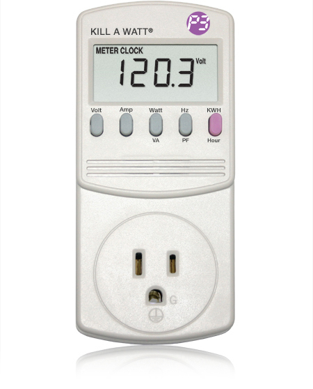 |
| Kill-a-Watt Meter |
Simply connect appliances to the Kill A WattTM, The LCD display shows consumption by the Kilowatt-hour, and also displays voltage (V), line current (Hz), current (I).
The first measurements I ran were on my Media Center setup which includes the following components:
- PC: My primary HTPC is built around Windows 7 Home Premium with Media Center. The hardware consists of a Biostar TH61-ITX Motherboard with Intel Core i3-2100 3.1GHz Processor, 8 MB of DDR3 RAM and 2 TB Western Digital Caviar Green Desktop Hard Drive.
- The TV is a Philips 47" LCD
- Speaker: Kenwood Sub-Woofer
- Normal Power-on Measurements (driving a full HDMI 1080P output at comfortable listening volume):
- HTPC = 54 Watts
- TV = 295 Watts
- Subwoofer = 76 Watts
- Sleep or "Standby" Mode Power Down measurements:
- HTPC = 3.4 Watts
- TV = 9 Watts
- Subwoofer = 16 Watts
The above results show that even during "Sleep Mode", the TV and the Subwoofer continue to draw 25 Watts of wasted "Phantom Power" when not in use! How much does this add up to in one year? The average cost of power is 7 cents per KWH in my region, so:
.025 KWH x (24 hours/day x 365 days/year) x $.07/KWH = $15 per year
All together the "sleep power" consumed by all 4 PC's around the house which have peripherals such as speakers, printers and or monitors connected to them, adds up to a fairly substantial waste of energy and money!
What can I do about this?
The obvious solution of course is to plug each item that is part of your PC setup into a common power strip with a single on/off switch. However, I wanted to find a lazy way to completely shut down the TV or monitor and other peripherals automatically and turn everything back on again using my Media Center remote control 10' away sitting on a couch. After some head-scratching and web-searching I found two commercial solutions, as well as the homebrew one described below.
Buy:
I found several "smart" power strips, all are available from Amazon that provide automatic sensing of the control outlet. When you power down your computer or stereo, these outlet strips shut down the power to your computer or entertainment center's peripherals. This unique feature not only saves you money and helps the environment, it also makes shutting down your systems fast and easy.
Click on the links below for further information:
 |
Smart Strip LCG3 Energy Saving Surge Protectorwith Autoswitching Technology |
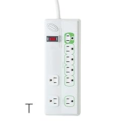 |
Globe 7815901 8-Outlet energy Saving Strip |
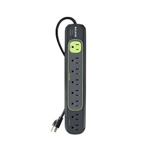 |
Belkin Conserve Socket with Energy-Saving Outlet |
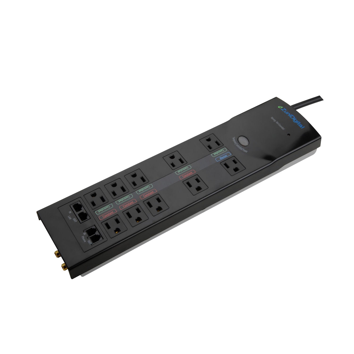 |
ZuniDigital ZG10222B-2710 Outlet Digital Smart Green Surge Protector |
Do It Yourself:
All three of the above commercial units look like they will do the job, but for the more technically inclined, I am also describing the Power Saver Box I built below.
It has a single AC "control" socket for the PC, and two or more "slave" sockets for peripherals such as the TV or monitor, printer, speaker amplifier, etc.
In operation when the PC goes to sleep the Power Saver box automatically shuts down those slave devices that would otherwise remain on, or in standby mode. This design features an adjustable threshold adjustment that can be tailored to the standby power characteristics of your master device. If you are technically inclined, here are further details on its operation and construction:
| TA20FL Current Transformer |
- Non-Intrusive Power Sensing: The PC serves as the control device, so it must always have power applied in order to be turned on or put to sleep via the Media Center's remote control or the PC's standby function. At the heart of the Power Saver is a small passive Current Transformer (CT) component. This device is basically an epoxy encapsulated toroid with 2000 turns of wire that serve as the transformer's secondary windings. So only a few turns of "primary" winding are needed through its 1/2" inner core hole to produce a useful voltage at its secondary output. Feeding two turns of the AC line's HOT wire through the CT allows the small differences in current draw between sleep mode and full power to be sensed by the transformer's sensitive secondary windings as a small AC voltage. This voltage is converted to DC and sent to a small circuit board that contains the necessary components to drive a solid state relay which controls AC power to the required peripheral devices.
 |
| SSR-25DA Solid State Relay |
- The prototype unit (Fig. 1) is housed in a salvaged 7" x 4" x 2" Pyxis Cubie prescription box. The simple control circuitry is mounted on a 2" x 3" perf. board shown within the dotted lines in Fig. 2. I mounted the circuit board directly to the inexpensive solid state relay module via its 4 terminal screws. I removed the 4 original screws and added longer screws and 1/4" stand-offs in order to clear the wiring on the underside of the circuit board.
- Precautions: Since this box plugs into the AC line I was careful to follow good wiring practice in building this unit. I also added a small small surge protecter box ahead of the main unit's power cord. Approach this project with care!
- Threshold Settings: The unit continously senses the PC's power draw. For my setup, it automatically shuts off the slave outlets when the power drops below 10 Watts - this happens when the PC is put to sleep using my remote control. When the PC turns on or resumes from sleep, power is applied to the peripherals as soon as the power draw goes above 40 Watts. An on-board potentiometer R3 allows fine adjustment of the ON/OFF power thresholds, shown in the graph of Fig. 3..
- An optional Bypass Switch SW1 allows the slave units to be forced on independently of the Master PC. This may be required for testing purposes, or in my case after a power failure, or if I pull the plug on the main unit. In this case I need a way to turn the TV on before turning on the PC to allow the TV's HDMI port to be recognized by the Windows OS. This switch is kept OFF during normal "standby" operation.
- The circuit diagram of the perf. board shows the current transformer's secondary output going to a voltage doubler rectifier. The resulting DC output is limited at 14 volts by zener diode D3 and then goes to the 1/3 & 2/3 threshold inputs of IC1, a TLC555C CMOS version of the common NE555 Timer chip. This device is used as a fixed hyterisis Schmidt Trigger to turn the relay control pins ON at output pin 7 when the input voltage reaches 2/3 Vcc and and OFF when input falls below 1/3 Vcc. RL1 is an inexpensive 25A solid-state relay that switches the two accessory devices. Potentiometer R3 allows vernier adjustment of the threshold detection input voltage for even lower power motherboards.
- The graph in Fig. 3 shows the power response curve for this circuit.
 |
| Figure 1. Power Saver Box |
 |
| Figure 2. Schematic Diagram |
 |
| Figure 3. Power Curve |
Very interesting post. I like to share this post with my friends and book mark this interesting page. Keep it up.
ReplyDeleteI guess I’m not a redneck woman? I can honestly say I want none of these…
ReplyDelete