 |
Heath Zenith Motion-Sensing Flood Security Light |
 |
Replacement Motion Sensor Head |
What's Missing: A nightime audible alert feature with remote monitoring option
Unavailable in commercially available units is some form of a "short single beep" audible alarm to scare off particularly stubborn intruders and large animals; it should also warn me remotely of intrusions into the back yard, or when someone pulls into the driveway at night. Following is my "wish list" of requirements for a suitable unit:
- It should be simple and fun to build and a cost less than unit(s) currently on the market.
- It should attach easily on to the existing motion sensors that I already have installed around the house.
- It should sound only once at the beginning when the lamps come on. Ideally, the audible alarm should be loud enough to be heard a short distance away to scare away intruders, but not to disturb neighbors.
- It should allow the intrusion to be monitored from within the house. At first I assumed that the beep would be loud enough to be heard at some distance from the sensor head, but I later realized that the only way to accomplish this would be to have a wireless remote monitor unit installed indoors.
- The indoors monitor unit should produce an audible beep - ideally the beep duration should be different for each sensor. It should also provide a visual indication of which of the motion sensors has been activated via a different colored LED for each motion sensor.
Here are a couple of solutions:
 |
DIY "Basic Beeper" |
2. A Flexible Wireless Remote Intrusion Monitoring System:
 |
| 433 MHz Motion Sensor Sending Unit |
 |
| Indoor Receiver Monitor |
It quickly became apparent that several of the Basic Beepers I installed were inaudible from inside the house. To solve this I came up with the following simple wireless remote monitoring system comprised of two basic modules - A 433Mhz Transmitter Sending Module (shown below) connected to each of the existing motion sensor heads, and one or more Remote Wireless Receiver Monitor boxes (see below) located indoors. Each monitor box consists of a simple low-cost RF receiver module connected to a small piezo-electric beeper and multicolored indicator LEDs that monitor the status of up to 8 remote devices, which can be the above-mentioned motion sensor lights, or optionally, several magnetic intrusion sensing switches that may be attached to exterior gates, doors or windows. For further details on the Wireless Monitoring System go here.
Getting Started - Understanding the Motion Sensor's Wiring:
 |
| Heath / Zenith Sensor Head Wiring Diagram (Wiring is the same for the stand-alone Replacement Sensor) |
I first needed to figure out how to tie my alert into the motion sensor's wiring. Most commercial units come pre-wired with a sensor head and two lamp sockets. I used the stand-alone replacement motion sensor unit instead for my two existing wall-mounted driveway lamps. Wiring for both types should be the same. I mounted the sensor head separately to a 4" round electrical receptacle purchased at Home Depot in an unobtrusive location away from the lights themselves. Either type of sensor head has an extra red control wire in addition to the black (HOT) and white (NEUTRAL) wires coming out of it. The lampheads, or any optional load, must be connected between the RED and WHITE leads. According to the manufacturer, a small additional load can also be connected across these 2 wires.
On my unit the total load including the two lamp heads should not exceed 500W (or 4.2 A). Refer to the wiring diagram above.
The RED control wire has full line voltage applied to it only when the motion sensor activates. I connected the 2 wires of my alert across the RED and WHITE wires.
NOTE: Many motion sensors are intended to drive incandescent lamps and use TRIACs instead of relays in their output circuit. They may have difficulty driving inductive loads such as AC relays, LED bulbs or the 110V to 12V step-down transformer used in the Beeper. In such cases I add a simple Snubber circuit (refer to this link for design detail) consisting of a "Class-X2" rated 0.47uF/ 275VAC capacitor in series with a 51 ohm/5 Watt resistor. After soldering these 2 components together in series, make sure they are completely insulated with shrink tubing, and then connect the two ends of the series combination across the RED (load) and WHITE (neutral) leads of the motion sensor.
NOTE: Many motion sensors are intended to drive incandescent lamps and use TRIACs instead of relays in their output circuit. They may have difficulty driving inductive loads such as AC relays, LED bulbs or the 110V to 12V step-down transformer used in the Beeper. In such cases I add a simple Snubber circuit (refer to this link for design detail) consisting of a "Class-X2" rated 0.47uF/ 275VAC capacitor in series with a 51 ohm/5 Watt resistor. After soldering these 2 components together in series, make sure they are completely insulated with shrink tubing, and then connect the two ends of the series combination across the RED (load) and WHITE (neutral) leads of the motion sensor.
1. The Basic Beeper
If you don't need any remote monitoring, then one of the 2 basic versions shown below should work for you. The 2 circuits differ in the method used to derive the 12 to 15 Volts DC from the 117 Volt AC line. There are many power supply options for this, the easiest is to use a standard AC to 12VDC wall mounted power module - A quality, well-regulated power source produces the cleanest beep.The first version (Fig.1) includes a transformer-isolated full-wave regulated power supply, and the second "transformerless" version is shown in Fig. 2. Other than the power supply and regulator, both versions require only 5 to 7 inexpensive components, including the volume control Rv. All these are available online through Amazon or eBay.
 |
| Auto Backup Alarm |
 |
| Piezoelectric Buzzer |
How it Works:
As an inital experiment I attached a small 117 VAC to 12-14 Volt DC "wallwart" power supply directly to the beeper, and obtained a very loud continous beep. In order to get the single initial beep I needed, I took advantage of a basic property of an R-C (Resistive/Capacitive) circuit that sees a large fully discharged capacitor as a short circuit before charging up exponentially to full charge with an applied voltage in time (seconds) = R (ohms) x C (farads). This feature provides a brief burst of full current to the beeper, the capacitor then charges up to full voltage and the current to the beeper drops to zero.
Unfortunately, once the capacitor charges up fully and the motion sensor shuts off, the capacitor continues to hold its charge. This is the result of the very high OFF resistance path through the reversed-biased rectifier diodes in the circuit, and the high reverse resistance of the beeper itself. When the sensor comes on again, the beeper refuses to sound. This problem is easily solved by adding a diode and resistor across the capacitor C1 (fig. 1) or C3 (fig. 2) to provide a discharge path as soon as sensor power shuts off. This allows the beep box to be fully armed and ready to go before the motion sensor comes back on again.
 |
| Fig. 1: Transformer Isolated Beeper for Commercial Motion Sensors |
Fig. 1 illustrates the "safe" transformer based version. It features a 12 volt voltage regulated power supply, or alternatively, a transformer-isolated AC to DC "WallWart" power supply with sufficient power to drive the much louder auto backup alarm.

Fig. 2: Transformerless Beeper for Motion Sensors
(Click to enlarge)Fig. 2 illustrates the more compact "transformerless" version that utilizes the capacitive reactance of a "Class-X" rated" 0.47uF capacitor combined with surge limiting resistor R1 and two back-to-back Zener diodes D1, D2 to drop the AC line voltage down to approximately 15 Volts at 15mA. This output current is sufficent to drive a small low-power efficient piezoelectric buzzer that produces a fairly loud 3 KHz high pitched beep. Zener diodes D1, D2 are also connected in a bridge configuration with two "normal" diodes D3, D4 in such a way that each of the 2 opposing Zener diodes D1, D2 acts as a Zener reference diode during one 1/2 cycle of the AC waveform, and as a normal forward-conducting diode during the other half, producing approximately (15 - 0.6) Volts D.C. across the output of the bridge. During the positive 1/2 cycle, current flows from the Hot AC line via Zener D3 through the load and back to the Neutral line via D2. During the negative half cycle it flows in the opposite direction from the Neutral line via Zener D4 through the load and back up to the Hot line via D1. .Warning! Even though transformerless circuits are commonly used within many commercial motion sensor units, be aware that such circuits are connected directly to the AC mains supply! When the power supply is connected as shown, the negative rail is 0.7v above neutral through forward biased zener diode D2. Using a line tester with respect to earth ground, make sure that your HOT and NEUTRAL wires are hooked up correctly. If the Hot and Neutral lines are accidentally reversed, the negative rail will be 170v (peak) above the hot line and the current flow through the diode will be lethal and can kill! Irregardless of hookup, you should never come in contact with any part of this circuit. It is essential that this unit be housed within a suitably insulated enclosure. The completed unit is enclosed in a SERPAC WM033 plastic box.
2. A Flexible Wireless 8-sensor Intrusion Monitoring System
The Wireless Monitoring System consists of a homemade RF Transmitter Module connected to each Motion Sensor Head and a Central Receiver Monitor Box mounted indoors. I built several small circuit boards containing an inexpensive 433 MHz RF transmitter module and a digital encoder IC which I mounted inside small weather-proof plastic boxes powered by a small 12-volt AC Charger Module. I attached each one to the control and neutral leads of my Motion Sensing Security Lights. Now whenever any of the outside motion sensor lights comes on, its sensor head transmits an encoded RF signal to the Indoor Monitor Box which sounds a short beep and lights the associated color LED for the duration of the motion sensor lamp's ON time.
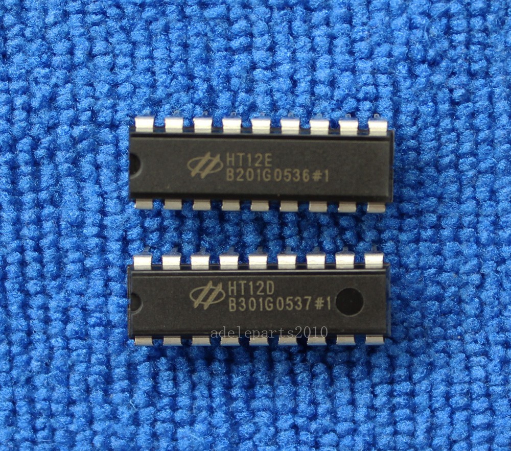
Holtek Encoder / Decoder IC pair 
433 MHz Transmitter / Receiver Kit from Amazon
The Transmitter/Receiver design utilizes a pair of very inexpensive 433 MHz RF Transmitter + Receiver Link modules that I purchased from Amazon. I have previously used these on Arduino wireless projects - similar units are also widely available on eBay. These units worked well over a range of 50 feet with a simple 1/4-wave straight wire antenna 6.8" long. I was able to increase the transmitter's range significantly by using the simple Deep Dish Cylindrical Parabolic Antenna described at: http://www.freeantennas.com/projects/template/ (see photo above of transmitter with antenna).The transmitter module is driven by the output of a Holtek HT12E CMOS Encoder IC, and the receiver module drives a matching Holtek HT12D CMOS Decoder IC. A pin-equivalent Encoder / Decoder IC pair made by SilvanChip is the SC2262 Encoder IC and the SC2272 Decoder IC; these are widely available on eBay.

Transmitter Module detail 
Fig. 3: Sensor Head Transmitter Module
(click to enlarge)Transmitter Circuit (Fig. 3):
Each Transmitter box contains a Holtek HT12E CMOS Encoder IC which drives a small 433 MHz RF transmitter module. When the motion sensor activates, it supplies power to the box, thereby asserting the TE/ (Transmit Enable) pin of the Encoder chip low. This generates an encoded pulse train containing an 8-bit address hard-wired code (A0 to A7). Note: In order to receive the encoded data correctly, the decoder chip in the Monitor Box must also be hard-wired with the same 8-bit address code as on the transmitter.
A unique 4-bit data word (D8 to D11) is also part of the serial data stream that is sent out to the RF transmitter module. Three of these 4 input data bits (D8 to D11) go to a 3-pin jumper plug that generates each sensor head's unique binary ID code (000 to 111). This code is decoded at the Receiver end and used to light the appropriate Sensor's LED. The 4th data bit input (D8) is wired to an RC (resistor/capacitor) network (R4 and C3 shown in Fig.3). The resulting time constant inserts a momentary "0" into the encoder's serial data word before its input pin charges up to a "1". This pulsed bit is decoded at the receiver to sound a brief "beep" at the beginning of the Sensor's ON period. The 4th LSB data bit (D8) at the HT12D encoder's output goes low only for a duration determined by the time constant of the resistor/capacitor (R4 and C3 in Fig.3) connected to the input pin of the transmitter's HT12E chip located in each of the 1 to 8 sensor heads. This low pulse is connected via a 2N3906 PNP transistor to an inexpensive piezoelectric beeper which produces a single adjustable volume "beep".

Fig. 4: 3-Sensor Monitor Receiver
(click to enlarge)
Receiver Circuit (Fig. 4): The monitor receiver consists of 1 (or more) small boxes powered by small readily available 5-volt USB cell-phone charger modules, and located indoors in various locations (I placed mine in the bedroom and kitchen). Each unit remains in a low-power standby state until it receives an RF signal from any of the 1 to 8 ensor transmitter heads. Each homemade receiver module consists of a tiny little low-cost 433MHz super-regenerative receiver module, plus two decoder / demultiplexer ICs. The receiver module demodulates the data stream and passes it on to a Holtek HT12D decoder IC. This chip strips off the repeating serial word consisting of 8 address bits and 4 data bits (D8 to D11) representing the unique binary coded state of the particular sensor head. If the 8 transmitted address bits (A0 - A7) match the 8 hard-wired address input pins of the decoder IC, then the decoder's VT (Valid Transmission) pin goes high and the 4 data bits are latched. Three of the 4 data bits (D9 to D11) are then passed on to the 3 input address bits of a 74HC138 3 to 8 decoder chip, which also serves as a buffer to drive the LEDs. The HT12D's VT signal goes to the positive enable pin (E3 ) of the 3 to 8 decoder. Depending on which sensor head's signal is being received, a "0" will be asserted at one of the 74HC138's eight output pins which are connected to a maximum of 8 different colored LEDs on the Monitor Box labeled SENSOR#1 through SENSOR#8. The corresponding sensor's LED will light up for the duration of the valid transmission.
Receiver is built inside a small Altoids can
Other Ideas
Adding multiple Sensor Monitor Boxes Indoors: All the components I used for this project are inexpensive and readily available. Several identical receiver boxes with matching address codes can be installed at very low cost in various parts of the house, such as the bedroom, kitchen, basement, office, etc. Each box will sound an adjustable volume beep and light a different colored LED corresponding to the motion sensor that was triggered.
Multi-colored LEDs from Amazon
Centralized Outdoor Intruder Alert: You can also install one or more receiver boxes in a more effective location outdoors to serve as the central audible intruder alert that will sound for up to 8 Motion Sensors Lights or other intruder sensing switch contacts. You will need to build a receiver board with matching address and a beeper only. I suggest mounting these inside a weatherproof receiver box.- I mounted each of the remote transmitter "Heads" in a small plastic box and connected it to the associated Motion Sensor head's control and neutral leads via a 117 V to 12 VDC power adapter.


 |
| Solid State Relay controls large AC loads |
If you need help or more information about building your own "Beep Boxes" contact me at viewcrestechnology@gmail.com.